- Sun 10 May 2020
- prototyping
Teaser trailer
Introduction
CAD modeling for building things is awesome! However, when it comes to organic shapes, that cannot be made up of the typical squares and circles, even designers with an intermediate skill level start to struggle.
Luckily, 3D scanning can help to get 3D models of organically shaped objects.
Hence, I show you here how to utilise 3D scanning specifially for CAD modeling - and all that without the need for a GPU or a powerful PC. As an exemplary project that also solves one of my (not so important) problems, I set myself to design a box for my (organically shaped) PC mouse. This will help me to carry my PC mouse in my backpack more easily.
This is the agenda for this tutorial:
- Scan preparations.
- 3D scanning with Meshroom - an open-source photogrammetry software - using the free Google Cloud.
- 3D model post processing.
- Building a CAD model around the 3D scan - using Autodesk Fusion 360.
- Fabrication and assembly of the mouse box.
- Final product.
- Summary.
- Acknowledgments.
Scan preparations
Since we use photogrammetry here, the texture of the object to be scanned should be as feature-rich and dull as possible. If the object you plan to scan is shiny, you have to make sure to cover it in some non-shiny material: Some people use painter’s tape, special powder or simply flour if your object permits. Furthermore, as photogrammetry identifies features of your object, or generally speaking your whole scene, you should also make sure that the whole scene in which you take the photos is feature-rich.
As an example, I am scanning my portable computer mouse here. Since it is shiny, I covered it in painter’s tape that I removed later on again. Additionally, I drew random symbols on that painter’s tape to assist the photogrammetry software to find distinct features that can be matched throughout the set of pictures.
Video 1: All photos of the PC mouse rendered into one video. The individual picture quality has been reduced for this video in order to ensure a reasonably small video file size. The quality of the images used for the 3D scan, however, has not been reduced in any way as to get the highest scan quality.
The animation in Vid. 1 shows a video of all the images that I used for the photogrammetry procedure. As you can see in Vid. 1, I made sure to cover the object in all possible angles, even multiple times and including close-ups of sections that might need additional coverage. To ensure enough distinct features in the scene, I designed an A4 sheet printout with random symbols on it: You can download it here to print the PDF yourself.
For the whole set of images I used a phone camera. I shot it outside on a cloudy day to guarantee an even lighting as photogrammetry does not cope well with hard shadows.
3D scanning with Meshroom
I use the free and amazing software Meshroom (https://alicevision.org/ and https://github.com/alicevision/meshroom) to perform the 3D scan of the PC mouse, see Fig. 1 for a screenshot of Meshroom. There are great tutorials on Meshroom out there. I used, for example, this one: https://www.youtube.com/watch?v=k4NTf0hMjtY.
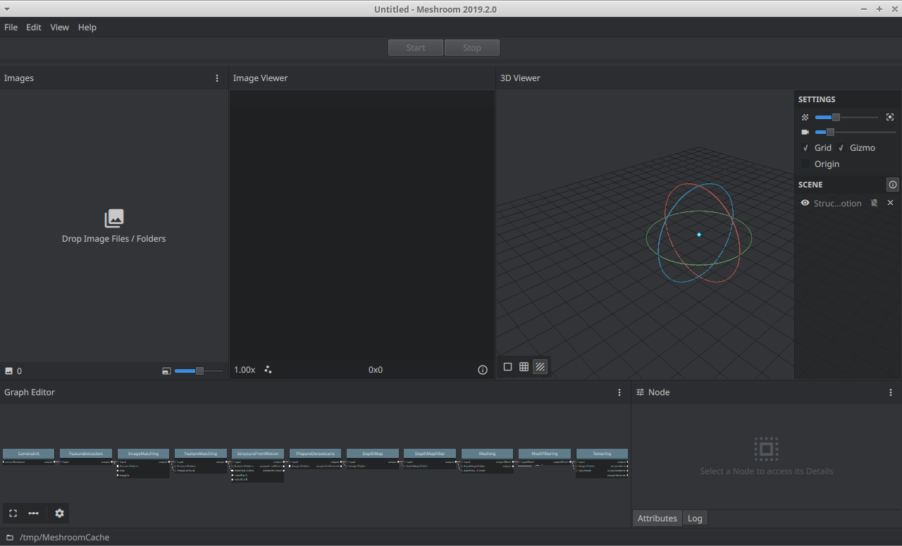
Figure 1: Meshroom version 2019.2.0 GUI screenshot. The whole computation performed by Meshroom is defined by the “Graph Editor” in the bottom and consumes pictures imported into the “Images” area. The final result is shown in the “3D Viewer”.
Unfortunately, Meshroom requires a CUDA-capable (i.e. somewhat powerful) GPU to yield the best 3D scanning results. In the following, I show how to run Meshroom (a) without a GPU on your computer at the cost of lower scan quality and (b) in the Google cloud on Google Colab for free at the cost of lacking a GUI. The GUI of Meshroom is well thought through and only executes underlying binary command line tools that can also be invoked without the GUI. Most of what I am stating here is knowledge collected from the internet so that I can redirect you to the original sources for in-depth explanations. In the following paragraphs, I expect you to have watched some tutorial on Meshroom as a dedicated tutorial will explain the details of Meshroom much better than I could ever do here.
To run Meshroom on your computer without a GPU you should check out this page. Also this resource is very good. In summary, you remove some of the default steps from the Meshroom computation pipeline, the depth map computation to be specific, in order to remove the computation steps that require a GPU. Depending on your computer hardware, the computation might only take a few minutes with these settings. The scan of my mouse with this technique is shown in Fig. 2 (b).
Next, we look into how to run Meshroom in the cloud on a GPU - for free. The scan of my mouse with this technique is shown in Fig. 2 (a). The procedure is as follows: You start a Google Colab instance, add a GPU runtime, upload your images and start the Meshroom commandline binary after downloading it. Since Google Colab runs with Jupyter Notebooks, all these tasks can be performed easily. Please check out the following notebook that I put together for you in order to start using Google Colab for 3D scanning right now: click. I based my notebook off publicly available information, such as this. My notebook works as follows:
- The pictures must be uploaded to the Colab instance as “my_dataset.zip”.
- Subsequently, they are automatically unzipped, processed and finally the 3D scan is zipped to be downloaded.
- My notebook is quite straightforward and well documented. Therefore, check out my comments and texts in the Jupyter notebook.
The 3D scan is saved by Meshroom as an OBJ file that includes both 3D mesh information as well as the texture of the object. Figure 2 shows the results of the 3D scan for both of the approaches, with and without GPU, respectively.
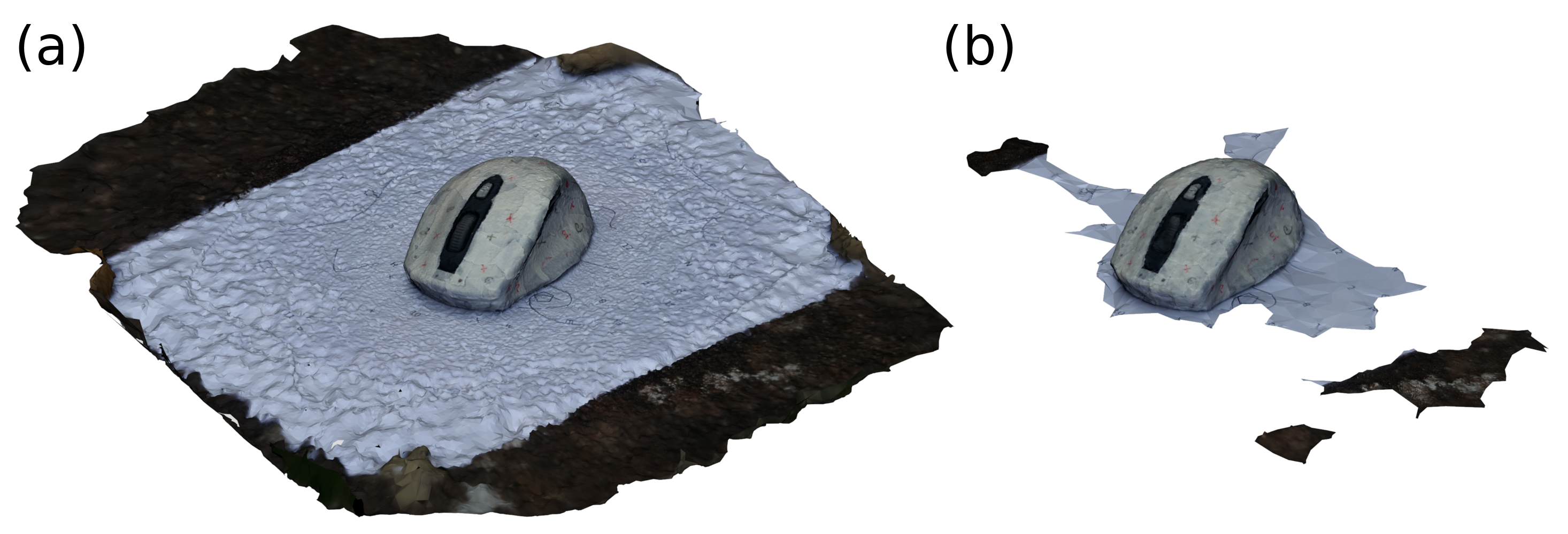
Figure 2: 3D scans of my PC mouse using Meshroom. (a) Scan result using a cloud GPU to enable the full computation pipeline & highest quality of Meshroom. (b) Scan result using Meshroom’s CPU-only computation steps.
While the CPU-only computation pipeline is quicker to compute and executable on any computer, the GPU-enabled features of Meshroom do increase the quality of the 3D scan significantly. They require a GPU and take slightly longer to compute, on the order of one hour vs on the order of minutes. Figure 2 might not be able to convey the detailed differences between the models, as it is just an image, but the GPU-enabled scan is much more detailed than the CPU-only scan: The CPU-only model consists of 43,512 scanned faces while the GPU-enabled scan consists of 1,043,705 scanned faces. Hence, the GPU-enabled scan detected almost 20x more faces than the CPU-only model using the exact same pictures of the PC mouse.
Therefore, I recommend to always use a GPU to compute Meshroom 3D scans, in particular taking Google Colab into account as it offers free GPU compute power.
3D model post processing
As photogrammetry identifies features in the images that are used in order to derive the camera perspectives, the scans might pick up parts of the scene in which the scan is created. I used a custom-made printout to ensure that there are enough distinct features. Figure 3 (a) shows the raw scan that comes out of Meshroom using the GPU-enabled computation pipeline executed on Google Colab and Fig. 3 (b) shows the same scan but a manually tidied up version of it. I used Blender to remove all excess parts of the scan that are not of relevance.
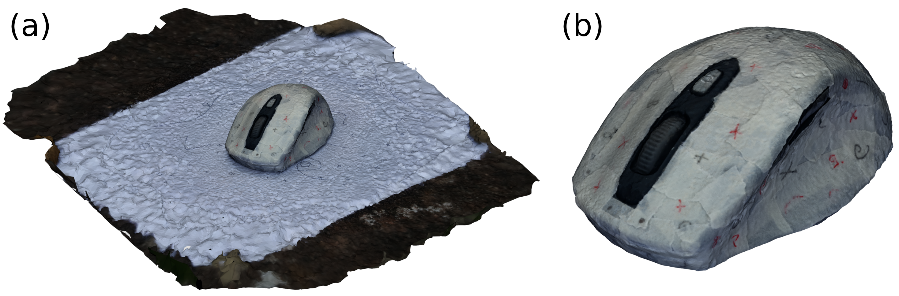
Figure 3: Cleaned 3D scan. (a) The model as computed by Meshroom. (b) Manually trimmed model to only consist of the mouse itself and no more scene parts.
Clearly, removing the artefacts is a mandatory step here. Depending on what you want to do with your scanned model, there is another mandatory step: Reducing the complexity of the 3D model by removing vertices. The original model as shown in Fig. 3 (a) consists of 1,043,705 faces and the trimmed model in Fig. 3 (b) consists of only 423,706 faces without reducing the model quality at all as only the excess parts of the scan were removed. For many applications though, even these 400k faces are too many. One such application being (consumer-grade) CADs (on a consumer-grade PC), I removed the number of faces even further before exporting the model to an STL file. Figure 4 shows exactly that.
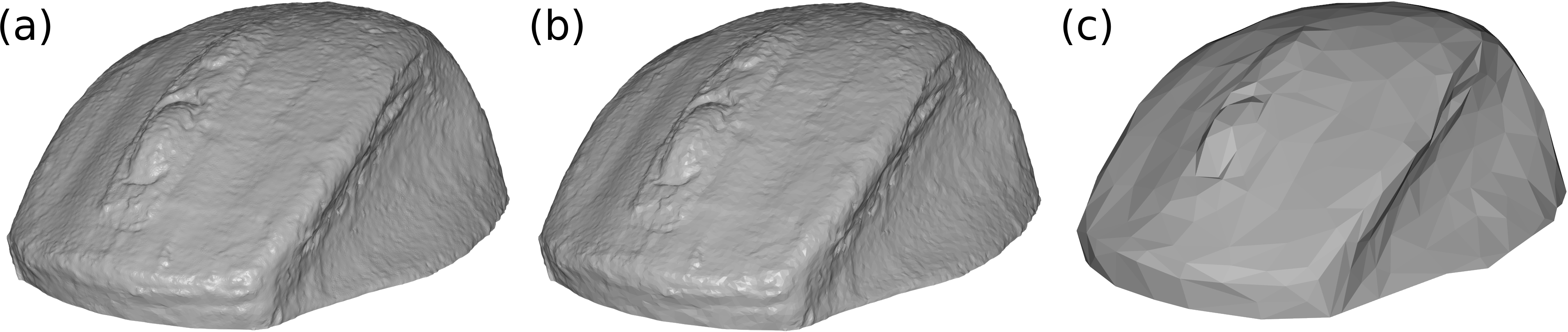
Figure 4: STL models of my scanned PC mouse after reducing the number of faces. (a) The original file as shown in Fig. 3 (b) after exporting it to STL (and, hence, without texture) with 423,706 faces. (b) STL with the number of faces reduced to 15% of the original model. (c) STL with the number of faces reduced to 0.15% of the original model. Subfigures (b) and (c) were generated with Blender by using its decimate modifier.
Since I wanted to use the model to design a box around it, I needed it in CAD. Most of the CAD software support generic model formats like STL or OBJ but can also transform these formats to their native data format. These two resources show how to transform an STL to Fusion 360’s native data format. This is very useful for all subsequent design steps but it comes at a high computational cost when the model is too detailed. Hence, I used the model shown in Fig. 4 (c) for being converted to a native Fusion 360 object and to model my PC mouse box around.
Building a CAD model around the 3D scan
I used the coarse-grained STL shown in Fig. 4 (c) to build my box around it. To do so, I imported it into Fusion 360 - the CAD I am using here - and designed a wooden box around it. In order to take advantage of having the organic shape of my mouse in CAD, I designed custom 3D printed pieces as inserts for the wooden box to ensure that the mouse does not move around inside the box while carrying it on-the-go.
To have the full capabilities of Fusion at hand for my mouse 3D scan, I converted it into the native Fusion data format as mentioned in the previous section. With this, I was able to use my scan with all joints and features inside Fusion. My finished CAD model is shown in Vid. 2.
Video 2: Video of CAD model of the mouse transportation box. The 3D scanned model of my PC mouse is shown in black. White pieces are 3D printed plastic pieces from PLA and the wooden box is shown in wood-brown. The wooden box will be laser cut.
Fabrication and assembly of the mouse box
I made use of my private 3D printer to fabricate the organically shaped custom inner blocks for the wooden box. The wooden box itself, I fabricated on my small hobby laser cutter.
The assembly is achieved step-wise: First, I glued the 3D printed plastic pieces to the wooden sides of the box, see Fig. 5 (a). Subsequently, I glued these wooden sides together with painter’s tape, see Fig. 5 (b), to ensure that everything fits together before doing the final glue-up.
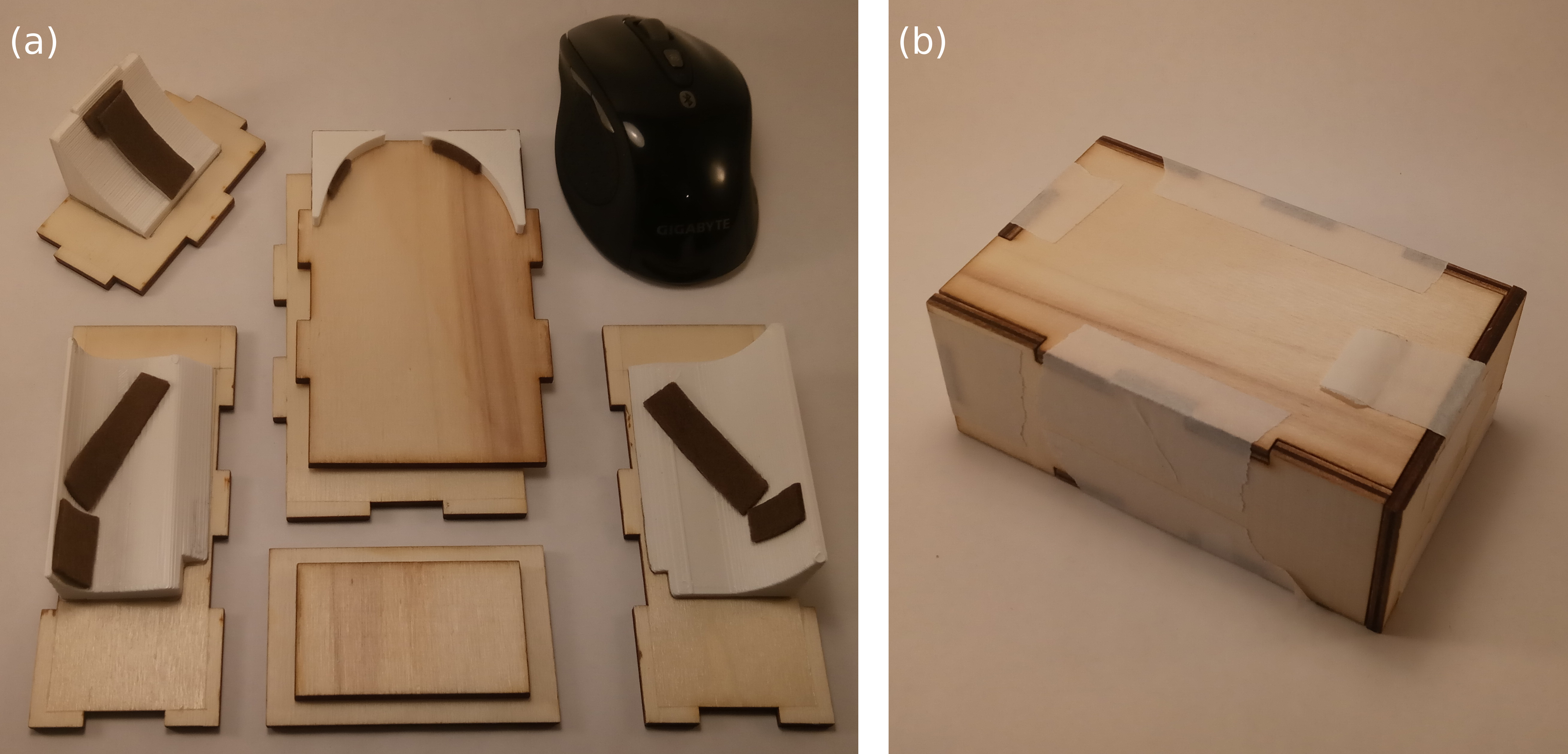
Figure 5: First two steps of assembly process. (a) Plastic pieces are glued to the wooden box sides and pads are attached to the 3D printed pieces to minimise the slag of the mouse inside the box and to avoid scratches on the mouse. (b) The wooden box as assembled temporarily with painter’s tape to ensure proper fitting.
Only after these two steps, I glued the wooden box sides into place with wood glue to achieve a permanently assembled wooden box, see Fig. 6 (a). Lastly, I applied clear coat to all of the wooden pieces, see Fig. 6 (b).
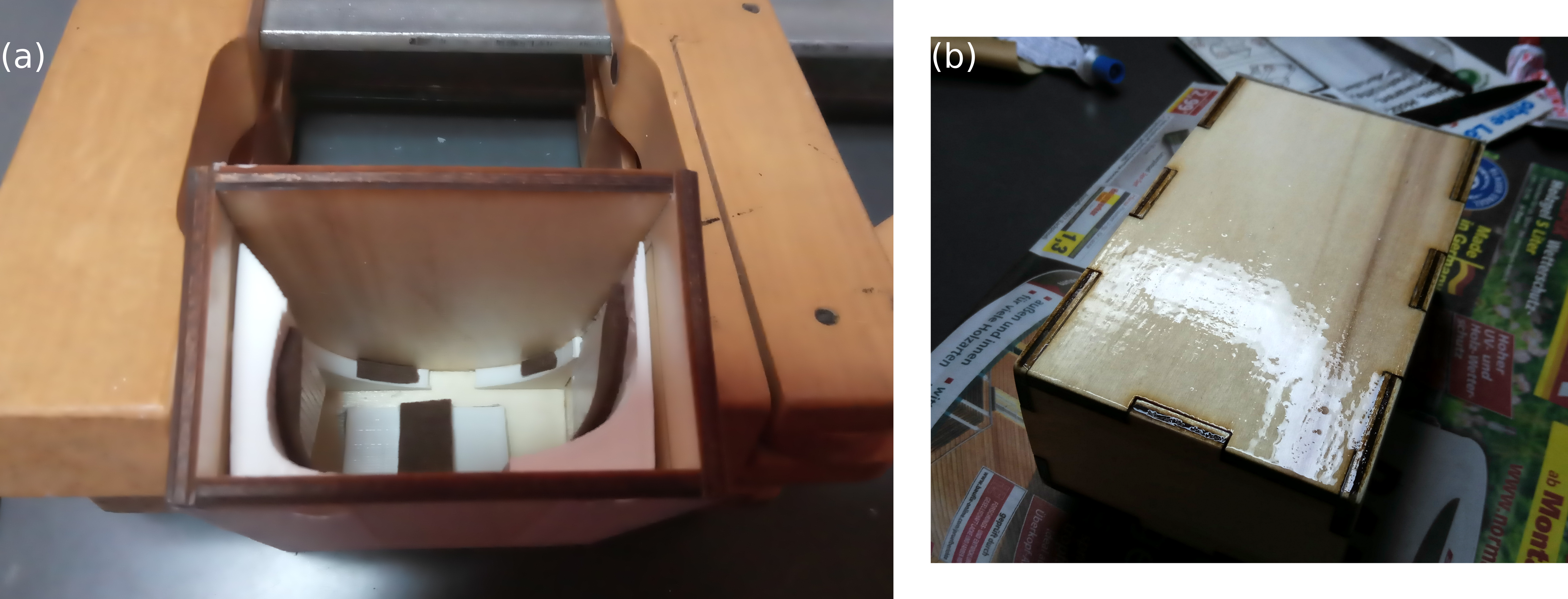
Figure 6: Next two steps of assembly process. (a) The permanent box glue-up with wood glue. (b) Application of liquid clear coat as finish and to make the box more sturdy.
As a next step, I prepared the wooden lid for the box using the laser cutter again. Afterwards I cut and glued the leather pieces in place that attach the lid to the main box body. There are three places that make use of the leather pieces: First, the piece that serves as hinge of the lid, second the strap to secure the lid to the box with a velcro and lastly another leather piece is placed symmetrically to leather hinge for aesthetic reasons. Figure 7 shows the finished leather parts.
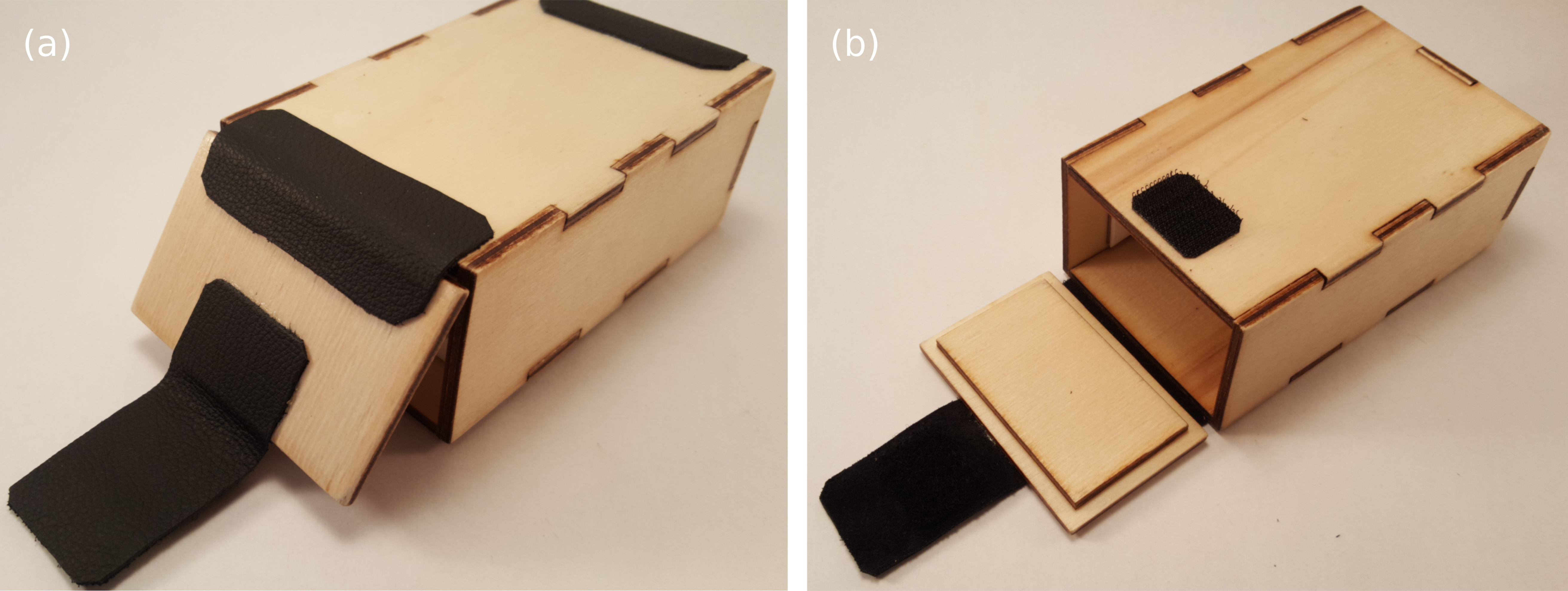
Figure 7: Mouse box with attached leather pieces. (a) Bottom view of the box to see all leather pieces installed. Going from left to right, the leather pieces serve as closing mechanism of the lid that uses a velcro, hinging mechanism of the lid and aesthetic sugar to the box. (b) Top view of the box with installed lid and leather pieces.
With that, the build is finished!
Final product
The finished product is shown in Fig. 8.
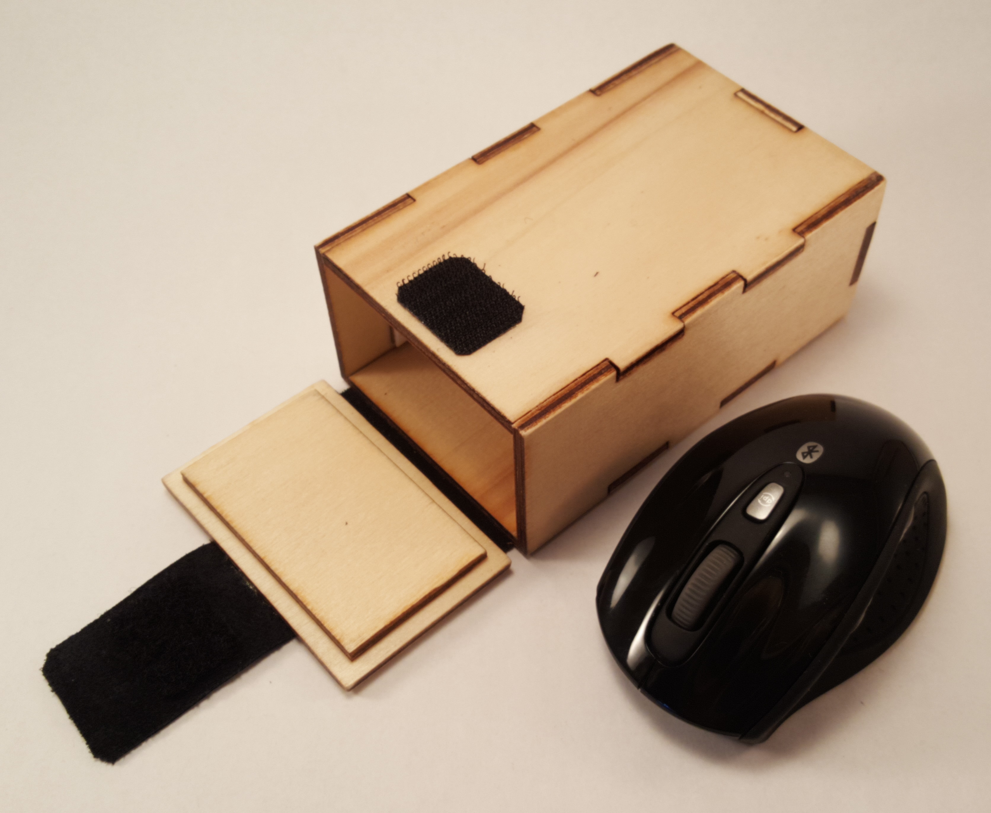
Figure 8: My PC mouse next to its new custom box. This is what I will use daily in my backpack from now on.
Lastly, let’s check out how the mouse itself likes its new box - see Vid. 3.
Video 3: My mouse checking out its new box. It appears to me that it likes its new accommodation.
Summary
In this article, I presented how the open-source 3D scanning software Meshroom can be used to produce 3D scans without a GPU using this Jupyter notebook and Google Colab. Subsequently, I showed how the 3D model can be used for CAD modeling. My demonstration use case was a transportation box for my PC mouse because it is a suitable object to be scanned and used in CAD.
The steps for obtaining a 3D scan that can be used for CAD modeling are shown in Fig. 9. While I explain the CAD-specific steps with Autodesk Fusion 360, similar steps apply for most CAD software that are on the market.

Figure 9: 3D scanning pipeline for obtaining a 3D model that can be used in CAD.
Particularly useful is the 3D scanning script for Google Colab that I provided. With that, you are not required to own a GPU-enabled PC anymore. Hence, the only thing you need to do to get your own 3D scan is to capture a set of pictures of the object you want to scan.
Happy scanning!
Acknowledgments
Thanks to Jens Wienkamp for letting me run my first Meshroom experiments on his GPU!